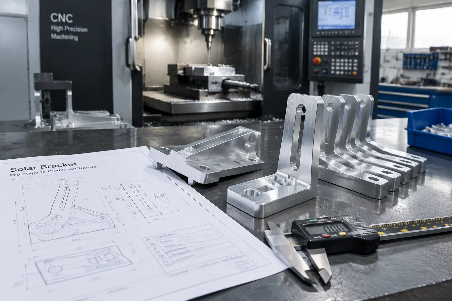
Engineering Background & Initial Defect Risks
Moving precision hardware components from single-unit functional testing into automated CNC mass production presents severe operational vulnerabilities. When Tuofa took on the fabrication of structural aluminum bracket assemblies for commercial solar arrays, initial CAD models revealed multiple tight radii and unchamfered internal pockets that functioned in isolation but threatened severe tool chatter under high-feed milling. Without a structured handoff rubric, design teams frequently pass CAD solids that machine shops interpret differently across toolpaths.
Claire Dupont audited the engineering transition workflow to determine why early trial runs exhibited non-uniform wall thickness and localized anodize pitting. The investigation isolated communication gaps between client CAD designers and shop-floor CAM programmers as the primary driver of rework. Tuofa implemented an interlocked Design for Manufacturability (DFM) verification lane, demanding shared tool clearance reviews and signed datum benchmarks before launching multi-axis workholding setups.
Aligning Hardware Prototyping With Machine Tool Realities
Schedule an engineering workflow session to audit design transfer lanes, inspection datums, and high-volume CNC tolerances.
Parametric Tolerances & Production Variance
Machine setup logs and coordinate measuring machine (CMM) reports from the pilot run demonstrated that nominal digital models differed substantially from post-thermal-treatment physical components. Establishing strict tolerance thresholds across four critical manufacturing indicators brought stability to the shop floor.
| Operational Parameter | Observed Specification | Target Benchmark |
|---|---|---|
| Internal Corner Radius | R0.5 mm sharp inner edge (high tool deflection) | R1.6 mm standardized fillet (allows Ø3.0 mm end mill) |
| Hole Center Position Tolerance | ±0.03 mm non-critical bolt holes | ±0.15 mm true position per ISO 2768-m |
| Anodized Surface Thickness | 12 μm to 38 μm uneven oxide layer | 20 μm to 25 μm Type II sulfuric bath control |
| First Article CMM Inspection Cycle | 4.2 hours per 10-piece pilot lot | 45 minutes automated probe cycle |
Multi-Tier Handoff Protocol & Verification
Achieving zero-rejection ramp-up required replacing fragmented email chains with immutable transfer logs. Tuofa introduced a formalized gatekeeper routine where customer engineering files pass through CAM simulation before metal stock touches vice jaws. This disciplined verification phase prevented unbudgeted cutter breakage and maintained machine spindle uptime above 91%.
Production Ramp Gatekeeper Checklist
Every batch transition enforces strict alignment across programming, stock preparation, and post-processing stations. The following controls govern the release from prototype bench to production cells:
- STEP AP242 model validation with explicit PMI annotation, confirming that datum references match physical fixtures on the 5-axis tombstone.
- Toolpath collision dry-run simulation using Vericut, preventing spindle-housing interference across dual-station rotational setups.
- Pre-treatment deburring and ultrasonic degreasing sign-off to ensure complete contaminant removal prior to sulfuric acid anodizing baths.